Solar tracker circuit diagram pdf
the solar tracker system as the initial step in producing the real solar tracker system. This This system may able to generate 100 Watt and can only move in a range of 45 degree to 135
Index Terms Solar tracker, Ar- duino ATmega 328, LDR, Single Axis ,Energy storage system . I. 2.1 BlOCK DIAGRAM: Arduino UNO Basic Information: The Arduino Uno is a microcontroller board based on the ATmega328.It has 14 digital input/output pins (of which 6 can be used as PWM outputs), 6 analog inputs, a 16 MHz ceramic resonator, a USB connection, a power jack, an ICSP header, and a reset
1.8.7 Portable Solar Tracker . 2.0 Background/Research 15 . 2.1 Display 15 1 Block diagram 5 2 Block Diagram of UCF FEC Team 11 3 Calbox 360 Project 13
Established for 6 years as a photovoltaic installer and manufacturer of solar trackers, we have created a branch specialized in the development and marketing of …
Solar Tracker Laboratory – Instructor Manual Figure 1: Simulink diagram used with QUARC to run the frequency response. Note to Instructors: The instructor can elect to …
Development of Dual-Axis Solar Tracking using Arduino with Lab VIEW K P J Pradeep1, K LEDs, and charts. The block diagram is a graphical representation of the underlying software program. It consists of icons that represent typical programming elements such as constants, variables, subroutines, and loops. Arduino is a single-board microcontroller, intended to make the application of
SOLAR TRACKER. INSTRUCTION SHEET . Solar Tracking kit Price – Stock No 215 Motors with Gearboxes Price – Stock No 750 3v Gearbox 2.93RPM – 3000 RPM (6 configurations) Price – Stock No 751 12V Gearbox 36 RPM Price – Stock No 752 12V Gearbox 70 RPM Price – Stock No 753 12V Gearbox 160 RPM As the name suggests this kit is designed to track the sun – for use with a solar …
tracker or the elevation in a dual axis solar tracker. Positioning the panel within a few degrees is often Positioning the panel within a few degrees is often acceptable so there are less move intervals over the course of the day.
Photovoltaic MPPT Charge Controller Amber Scheurer Ersuel Ago Juan Sebastian Hidalgo Steven Kobosko Group 10 Senior Design 1 Fall 2011 Mentor
Design of a Charge Controller Circuit with Maximum Power Point Tracker (MPPT) for Photovoltaic System A Thesis submitted to the Dept. of Electrical & Electronic Engineering, BRAC University in
Fig. 1: Circuit of solar tracking system Fig. 1 shows the circuit of the solar tracking system. The solar tracker comprises comparator IC LM339 , H-bridge motor driver …
Single axis solar tracker: Single axis solar tracker can either have a horizontal or a vertical axis. The horizontal The horizontal axis type used in tropical regions …
the + panel and cathode to the MPPT + input white wire) may be used, see wiring diagram. This diode will protect against panel short and block any voltage on …
diagram 2-1. Diagram 2-1 Solar module icon presents the numbers of MPP tracker defined by solar inverter. NOTE: Battery and load icon will not present only when this device is set as grid-tie mode. There are three operation modes can be set up via this software. Below is operation power flow description. Operation mode setting can be configured in MyPower Management. Please refer to …
NOTE: If your solar tracker doesn’t track the sun accurately, the solar cell may be receiving too much reflected light from low clouds, brightly painted walls, or other nearby surroundings. Try painting the shade black underneath, and/or taping over unneeded portions of the solar cell.
Rotary Experiment #16 Solar Tracker
Sun Tracker Circuit Healthy Discussion! 6 Steps
The solar tracker system requires movement in different directions , and uses electric motors as prime mover, based on this; solar tracker system motion control is simplified to
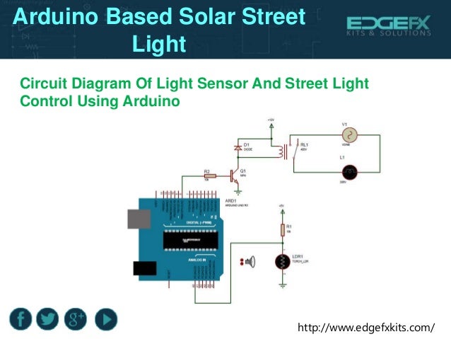
Circuit Diagram and Explanation: In this Arduino Solar Panel Tracker, Arduino is powered by the 9V battery and all the other parts are powered by the Arduino. Arduino recommended input voltage is from 7 to 12 volts but you can power it within the range of 6 to 20 volts which is the limit. Try to power it within the recommended input voltage. So connect the positive wire of the battery to the
EDL Project Report 2009 3 Circuit Diagram: Algorithm Implemented: The RTC gives the data of the current time continuously to the microcontroller.
When a panel heats up due to the sun shining on it, both the open circuit voltage and the Maximum Power Point voltage become lower. The current however remains practically constant.
analog solar tracker circuit schematic by Bien This is a simple and practical analog solar panel tracker circuit. Using four LDR (light dependent resistor) as a sensor in detecting the light source arranged as illustrated.
The main objective of this paper is to develop a microcontroller-based solar panel tracking system which will keep the solar panels aligned with the Sun in order to maximize in harvesting solar power.
T. Tudorache et al. Design of a Solar Tracker System for PV Power Plants – 24 – equipment is still one of top priorities for many academic and/or industrial
In order for this solar tracker to be controlled only by the sun’s movement throughout the solar cycle, a sensing circuit must be setup to replace the simple switch mentioned above in point
A single-axis solar tracker follows the movement of the sun from east to west by rotating the structure along the vertical axis. The solar panels are usually tilted at a fixed angle corresponding to the latitude of the location. According to [3], the use of single-axis tracking can in-crease the electricity yield by as much as 27 to 32 per-cent. On the other hand, a dual-axis solar tracker
Solar-power electronic circuits and electronic projects. Note that all these links are external and we cannot provide support on the circuits or offer any guarantees to their accuracy.
Sun Tracker Circuit – Healthy Discussion!: My apologies to any of the 1400 or so people who’ve read this Instructable in the day since it was published; I described an idea I was sure would work, and I was so excited to get it out there where people could try it, that I didn’t wait until I…
A typical solar panel power graph ( Figure 1) shows the open circuit voltage to the right of the maximum power point. The open circuit voltage (VOC) is obviously the maximum voltage that the panel outputs, but no power is drawn. The short-circuit current of the panel (I SC) is another important parameter, because it is the absolute maximum current you can get from the panel. Authors: Mihnea
Hey Tom, We are right now making a Solar sand sinter 3D printer. We have finished making the coordinate plate and are working on the tracking system now. Would like to get your inputs. Best, We have finished making the coordinate plate and are working on the tracking system now.
View Power 件介 MPP Solar
14/09/2014 · This video explains the automatic sun tracking solar panel details along with project abstract, circuit diagram and working functionality.
Simple Low Cost Solar Tracker System Circuit Diagram Using LM358 Simple Low Cost Solar Tracker System Circuit Diagram Using LM358 Solar Circuit. Explanations about solar trackers, and DIY tracker circuit schematics. Solar tracking devices maximize the energy collected by solar panel placing the It is low cost, has a simple design, and is easy to operate. There is a single Figure 1 …
Here is circuit diagram for the 4 Channel Relay module. It’s pretty easy to connect up. The arduino supplies power to the relay switches, but not the motors. You need to connect a power supply to the other side of the relays. I use a 12V DC power supply, but you could use whatever you like. Tip! – You could alter the voltage of this power supply to speed up or slow down your motors
diameter wire from the Solar Tracker Output directly to the battery system. Make sure Make sure the system inverter has its “over-voltage” protection point set at or above 15.4 volts.
A real solar tracking system can improve the electricity production of a solar panel [2], [3] up to 27 % for a double axis tracker and 23 % for a single
tracker was perpendicular to the light source by 1.5 degrees. The built system had a The built system had a calculated annual energy gain of 48.982% compared to an immobile solar panel.
Mobile Sun Tracking Solar Power Plant A recent storm with horrific winds took down our electrical power. The outage was widespread, straining the power company to get everyone back online.
16/06/2013 · This is a brilliant simple idea for a homemade solar tracking model using a few easily available components and minimal assembly at almost no cost.
DIY Solar Tracker System Circuit The solar panels are operating at optimal parameters when they are at the perfect right angle to the sun. Unfortunately this is accomplished only if solar …
Figure 10: Circuit design of solar tracker e) The PCB was placed into the ultraviolet (UV) exposure unit and exposed to UV-light for about 140 to 200 seconds. – accurate gps tracker user manual The solar panels will need to be placed in series and connected to the booster-circuit on the Solar Tracker-1 PC board, to produce the voltage required to charge the NiCads. You will need eight solar cells (100mA type) to produce a 4v solar panel or six solar cells (200mA type) to produce a 3v solar panel to maintain the charge in the NiCads
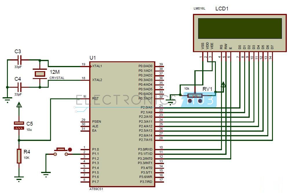
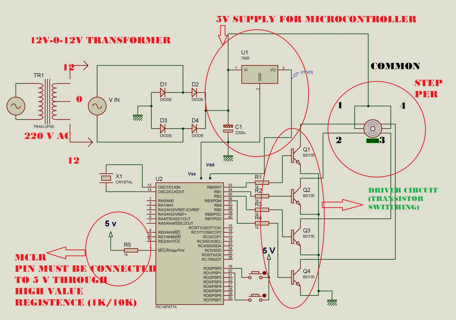
Resistance value of CdS at various illumination level of light Fig. 3 shows the schematic diagram of the prototype designed in Proteus 7 professional software. Schematic of solar tracker circuitry
position, maximizes output. 1. Introduction Figure 5. Circuit Diagram of the Single Axis Automatic Solar Tracker. 4. This video explains the automatic sun tracking solar panel details along with
Figure2. block diagram of the solar tracker 2.1 Solar Tracker A solar tracker is an electro-mechanical device for orienting a solar photovoltaic panel toward the sun trackers, especially in solar cell applications require a high degree of accuracy to ensure that the concentrated sunlight is directed precisely to the powered device. Solar trackers can be active or passive and may ARM Based
Intelligent Solar Tracker System Implemented On 8051 Microcontroller In the following block diagram, when sun rays fall on the LDR then according to intensity of light, it generates variable analog output. AT89S52 microcontroller will read data from the LDR through MCP3208 which is serial ADC used for converting analog signal to digital one. Oscillator gives the clock to microcontroller
Figure 1 shows the block diagram of a dual axis solar tracker. 4 LDR sensors are placed adjacent to the solar panel and will be activated when light is detected. An activate signal will be sent to the microcontroller and when the signal is received, the Arduino microcontroller will trigger the 2 drivers and activate the 2 motors. 2.2. AutoCAD AutoCAD is a computer-aided drafting software
4.7 Circuit Diagram 58 4.8 PIC Circuit 59 4.9 PIC16F877A Circuit components 59 4.10 ULN 60 4.11 Key Features of ULN 60 4.12 Control Algorithm 61 Chapter 5 Results and Discussions 5.1 Description of the Circuit used for Analysis 62 5.2 Results 62 5.3 To Calculate Enhancement by Employing Tracker 74 5.4 Discussions 75. viii Chapter 6 Conclusion and scope for future works 6.1 Conclusion 76 6.2
Solar Tracking Schematics Op Amp based solar tracker. The circuit is very accurate and would be right at home tracking. Solar tracking can be used for a variety of projects that require tracking solar …
Automatic Sun Tracking Solar Panel Project YouTube
Sun Path Diagram for 400 N Latitude During Winter and Summer Solstices For many years, several energy companies and research institutions have been performing solar tracking for improving the efficiency of solar energy production. A variety of techniques of solar energy production used have proven that up to 30% more solar energy can be collected with a solar tracker than with a fixed PV
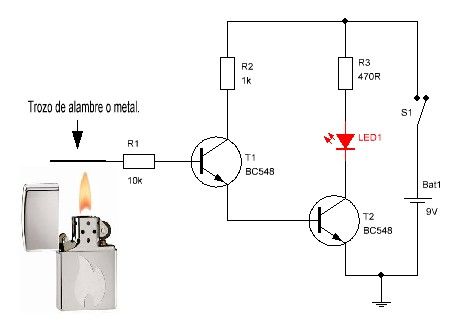
This circuit is a SOLAR TRACKER. It uses green LEDs to detect the sun and an H-Bridge to drive the motor. A green LED produces nearly 1v but only a fraction of a milliamp when sunlight is detected by the crystal inside the LED and this creates an imbalance in the circuit to drive the motor either clockwise or anticlockwise. The circuit will deliver about 300mA to the motor.
Practical guide to implementing Solar Panel MPPT Algorithms
Solar Tracking Schematics WordPress.com
Solar Tracking Schematic Diagram WordPress.com
Arduino Solar Tracker Electronic Circuits and Diagrams
Tesla Solar Tracker 5 Model # S3A12 Specification Sheet

Cool DIY Solar Tracker Self Powered No Electronics How
DIY Solar Tracker System Circuit Solar Energy Solar Panel
deloitte tmt predictions 2015 pdf – Solar Tracking Platform Make
Solar-power electronic circuits and electronic projects
Model 1700W Solar Battery Charger MPPT30-1 Maximum Power
Photovoltaic MPPT Charge Controller Departments of ECE
Development of Dual-Axis Solar Tracking using Arduino with Lab VIEW K P J Pradeep1, K LEDs, and charts. The block diagram is a graphical representation of the underlying software program. It consists of icons that represent typical programming elements such as constants, variables, subroutines, and loops. Arduino is a single-board microcontroller, intended to make the application of
Sun Path Diagram for 400 N Latitude During Winter and Summer Solstices For many years, several energy companies and research institutions have been performing solar tracking for improving the efficiency of solar energy production. A variety of techniques of solar energy production used have proven that up to 30% more solar energy can be collected with a solar tracker than with a fixed PV
A single-axis solar tracker follows the movement of the sun from east to west by rotating the structure along the vertical axis. The solar panels are usually tilted at a fixed angle corresponding to the latitude of the location. According to [3], the use of single-axis tracking can in-crease the electricity yield by as much as 27 to 32 per-cent. On the other hand, a dual-axis solar tracker
Solar-power electronic circuits and electronic projects. Note that all these links are external and we cannot provide support on the circuits or offer any guarantees to their accuracy.
T. Tudorache et al. Design of a Solar Tracker System for PV Power Plants – 24 – equipment is still one of top priorities for many academic and/or industrial
Single axis solar tracker: Single axis solar tracker can either have a horizontal or a vertical axis. The horizontal The horizontal axis type used in tropical regions …
1.8.7 Portable Solar Tracker . 2.0 Background/Research 15 . 2.1 Display 15 1 Block diagram 5 2 Block Diagram of UCF FEC Team 11 3 Calbox 360 Project 13
tracker or the elevation in a dual axis solar tracker. Positioning the panel within a few degrees is often Positioning the panel within a few degrees is often acceptable so there are less move intervals over the course of the day.
analog solar tracker circuit schematic by Bien This is a simple and practical analog solar panel tracker circuit. Using four LDR (light dependent resistor) as a sensor in detecting the light source arranged as illustrated.
The solar panels will need to be placed in series and connected to the booster-circuit on the Solar Tracker-1 PC board, to produce the voltage required to charge the NiCads. You will need eight solar cells (100mA type) to produce a 4v solar panel or six solar cells (200mA type) to produce a 3v solar panel to maintain the charge in the NiCads
diameter wire from the Solar Tracker Output directly to the battery system. Make sure Make sure the system inverter has its “over-voltage” protection point set at or above 15.4 volts.
Photovoltaic MPPT Charge Controller Amber Scheurer Ersuel Ago Juan Sebastian Hidalgo Steven Kobosko Group 10 Senior Design 1 Fall 2011 Mentor
16/06/2013 · This is a brilliant simple idea for a homemade solar tracking model using a few easily available components and minimal assembly at almost no cost.
Tesla Solar Tracker 5 Model # S3A12 Specification Sheet
Simple Solar Tracking Schematic
Established for 6 years as a photovoltaic installer and manufacturer of solar trackers, we have created a branch specialized in the development and marketing of …
SOLAR TRACKER. INSTRUCTION SHEET . Solar Tracking kit Price – Stock No 215 Motors with Gearboxes Price – Stock No 750 3v Gearbox 2.93RPM – 3000 RPM (6 configurations) Price – Stock No 751 12V Gearbox 36 RPM Price – Stock No 752 12V Gearbox 70 RPM Price – Stock No 753 12V Gearbox 160 RPM As the name suggests this kit is designed to track the sun – for use with a solar …
14/09/2014 · This video explains the automatic sun tracking solar panel details along with project abstract, circuit diagram and working functionality.
Sun Path Diagram for 400 N Latitude During Winter and Summer Solstices For many years, several energy companies and research institutions have been performing solar tracking for improving the efficiency of solar energy production. A variety of techniques of solar energy production used have proven that up to 30% more solar energy can be collected with a solar tracker than with a fixed PV
The main objective of this paper is to develop a microcontroller-based solar panel tracking system which will keep the solar panels aligned with the Sun in order to maximize in harvesting solar power.
the panel and cathode to the MPPT input white wire) may be used, see wiring diagram. This diode will protect against panel short and block any voltage on …
Circuit Diagram and Explanation: In this Arduino Solar Panel Tracker, Arduino is powered by the 9V battery and all the other parts are powered by the Arduino. Arduino recommended input voltage is from 7 to 12 volts but you can power it within the range of 6 to 20 volts which is the limit. Try to power it within the recommended input voltage. So connect the positive wire of the battery to the
1.8.7 Portable Solar Tracker . 2.0 Background/Research 15 . 2.1 Display 15 1 Block diagram 5 2 Block Diagram of UCF FEC Team 11 3 Calbox 360 Project 13
4.7 Circuit Diagram 58 4.8 PIC Circuit 59 4.9 PIC16F877A Circuit components 59 4.10 ULN 60 4.11 Key Features of ULN 60 4.12 Control Algorithm 61 Chapter 5 Results and Discussions 5.1 Description of the Circuit used for Analysis 62 5.2 Results 62 5.3 To Calculate Enhancement by Employing Tracker 74 5.4 Discussions 75. viii Chapter 6 Conclusion and scope for future works 6.1 Conclusion 76 6.2
Solar Tracking Schematic Diagram WordPress.com
Arduino Solar Tracker using LDR and Servo Circuit Digest
NOTE: If your solar tracker doesn’t track the sun accurately, the solar cell may be receiving too much reflected light from low clouds, brightly painted walls, or other nearby surroundings. Try painting the shade black underneath, and/or taping over unneeded portions of the solar cell.
When a panel heats up due to the sun shining on it, both the open circuit voltage and the Maximum Power Point voltage become lower. The current however remains practically constant.
The solar tracker system requires movement in different directions , and uses electric motors as prime mover, based on this; solar tracker system motion control is simplified to
A typical solar panel power graph ( Figure 1) shows the open circuit voltage to the right of the maximum power point. The open circuit voltage (VOC) is obviously the maximum voltage that the panel outputs, but no power is drawn. The short-circuit current of the panel (I SC) is another important parameter, because it is the absolute maximum current you can get from the panel. Authors: Mihnea
A real solar tracking system can improve the electricity production of a solar panel [2], [3] up to 27 % for a double axis tracker and 23 % for a single
Sun Path Diagram for 400 N Latitude During Winter and Summer Solstices For many years, several energy companies and research institutions have been performing solar tracking for improving the efficiency of solar energy production. A variety of techniques of solar energy production used have proven that up to 30% more solar energy can be collected with a solar tracker than with a fixed PV
Solar-power electronic circuits and electronic projects. Note that all these links are external and we cannot provide support on the circuits or offer any guarantees to their accuracy.
Development of Dual-Axis Solar Tracking using Arduino with Lab VIEW K P J Pradeep1, K LEDs, and charts. The block diagram is a graphical representation of the underlying software program. It consists of icons that represent typical programming elements such as constants, variables, subroutines, and loops. Arduino is a single-board microcontroller, intended to make the application of
Resistance value of CdS at various illumination level of light Fig. 3 shows the schematic diagram of the prototype designed in Proteus 7 professional software. Schematic of solar tracker circuitry
Simple Low Cost Solar Tracker System Circuit Diagram Using LM358 Simple Low Cost Solar Tracker System Circuit Diagram Using LM358 Solar Circuit. Explanations about solar trackers, and DIY tracker circuit schematics. Solar tracking devices maximize the energy collected by solar panel placing the It is low cost, has a simple design, and is easy to operate. There is a single Figure 1 …
Figure 1 shows the block diagram of a dual axis solar tracker. 4 LDR sensors are placed adjacent to the solar panel and will be activated when light is detected. An activate signal will be sent to the microcontroller and when the signal is received, the Arduino microcontroller will trigger the 2 drivers and activate the 2 motors. 2.2. AutoCAD AutoCAD is a computer-aided drafting software
diameter wire from the Solar Tracker Output directly to the battery system. Make sure Make sure the system inverter has its “over-voltage” protection point set at or above 15.4 volts.
Mobile Sun Tracking Solar Power Plant A recent storm with horrific winds took down our electrical power. The outage was widespread, straining the power company to get everyone back online.
View Power 件介 MPP Solar
Arduino Solar Tracker Electronic Circuits and Diagrams
diameter wire from the Solar Tracker Output directly to the battery system. Make sure Make sure the system inverter has its “over-voltage” protection point set at or above 15.4 volts.
A single-axis solar tracker follows the movement of the sun from east to west by rotating the structure along the vertical axis. The solar panels are usually tilted at a fixed angle corresponding to the latitude of the location. According to [3], the use of single-axis tracking can in-crease the electricity yield by as much as 27 to 32 per-cent. On the other hand, a dual-axis solar tracker
the solar tracker system as the initial step in producing the real solar tracker system. This This system may able to generate 100 Watt and can only move in a range of 45 degree to 135
Mobile Sun Tracking Solar Power Plant A recent storm with horrific winds took down our electrical power. The outage was widespread, straining the power company to get everyone back online.
14/09/2014 · This video explains the automatic sun tracking solar panel details along with project abstract, circuit diagram and working functionality.
Index Terms Solar tracker, Ar- duino ATmega 328, LDR, Single Axis ,Energy storage system . I. 2.1 BlOCK DIAGRAM: Arduino UNO Basic Information: The Arduino Uno is a microcontroller board based on the ATmega328.It has 14 digital input/output pins (of which 6 can be used as PWM outputs), 6 analog inputs, a 16 MHz ceramic resonator, a USB connection, a power jack, an ICSP header, and a reset
Established for 6 years as a photovoltaic installer and manufacturer of solar trackers, we have created a branch specialized in the development and marketing of …
The solar panels will need to be placed in series and connected to the booster-circuit on the Solar Tracker-1 PC board, to produce the voltage required to charge the NiCads. You will need eight solar cells (100mA type) to produce a 4v solar panel or six solar cells (200mA type) to produce a 3v solar panel to maintain the charge in the NiCads
Hey Tom, We are right now making a Solar sand sinter 3D printer. We have finished making the coordinate plate and are working on the tracking system now. Would like to get your inputs. Best, We have finished making the coordinate plate and are working on the tracking system now.
This circuit is a SOLAR TRACKER. It uses green LEDs to detect the sun and an H-Bridge to drive the motor. A green LED produces nearly 1v but only a fraction of a milliamp when sunlight is detected by the crystal inside the LED and this creates an imbalance in the circuit to drive the motor either clockwise or anticlockwise. The circuit will deliver about 300mA to the motor.
NOTE: If your solar tracker doesn’t track the sun accurately, the solar cell may be receiving too much reflected light from low clouds, brightly painted walls, or other nearby surroundings. Try painting the shade black underneath, and/or taping over unneeded portions of the solar cell.
tracker was perpendicular to the light source by 1.5 degrees. The built system had a The built system had a calculated annual energy gain of 48.982% compared to an immobile solar panel.
T. Tudorache et al. Design of a Solar Tracker System for PV Power Plants – 24 – equipment is still one of top priorities for many academic and/or industrial
Arduino Solar Tracker using LDR and Servo Circuit Digest
Automatic Sun Tracking Solar Panel Project YouTube
1.8.7 Portable Solar Tracker . 2.0 Background/Research 15 . 2.1 Display 15 1 Block diagram 5 2 Block Diagram of UCF FEC Team 11 3 Calbox 360 Project 13
EDL Project Report 2009 3 Circuit Diagram: Algorithm Implemented: The RTC gives the data of the current time continuously to the microcontroller.
Sun Tracker Circuit – Healthy Discussion!: My apologies to any of the 1400 or so people who’ve read this Instructable in the day since it was published; I described an idea I was sure would work, and I was so excited to get it out there where people could try it, that I didn’t wait until I…
Intelligent Solar Tracker System Implemented On 8051 Microcontroller In the following block diagram, when sun rays fall on the LDR then according to intensity of light, it generates variable analog output. AT89S52 microcontroller will read data from the LDR through MCP3208 which is serial ADC used for converting analog signal to digital one. Oscillator gives the clock to microcontroller
Circuit Diagram and Explanation: In this Arduino Solar Panel Tracker, Arduino is powered by the 9V battery and all the other parts are powered by the Arduino. Arduino recommended input voltage is from 7 to 12 volts but you can power it within the range of 6 to 20 volts which is the limit. Try to power it within the recommended input voltage. So connect the positive wire of the battery to the
analog solar tracker circuit schematic by Bien This is a simple and practical analog solar panel tracker circuit. Using four LDR (light dependent resistor) as a sensor in detecting the light source arranged as illustrated.
Mobile Sun Tracking Solar Power Plant A recent storm with horrific winds took down our electrical power. The outage was widespread, straining the power company to get everyone back online.
Single axis solar tracker: Single axis solar tracker can either have a horizontal or a vertical axis. The horizontal The horizontal axis type used in tropical regions …
Arduino Solar Tracker Electronic Circuits and Diagrams
Simple Solar Tracking Schematic
16/06/2013 · This is a brilliant simple idea for a homemade solar tracking model using a few easily available components and minimal assembly at almost no cost.
Figure2. block diagram of the solar tracker 2.1 Solar Tracker A solar tracker is an electro-mechanical device for orienting a solar photovoltaic panel toward the sun trackers, especially in solar cell applications require a high degree of accuracy to ensure that the concentrated sunlight is directed precisely to the powered device. Solar trackers can be active or passive and may ARM Based
Sun Tracker Circuit – Healthy Discussion!: My apologies to any of the 1400 or so people who’ve read this Instructable in the day since it was published; I described an idea I was sure would work, and I was so excited to get it out there where people could try it, that I didn’t wait until I…
1.8.7 Portable Solar Tracker . 2.0 Background/Research 15 . 2.1 Display 15 1 Block diagram 5 2 Block Diagram of UCF FEC Team 11 3 Calbox 360 Project 13
tracker was perpendicular to the light source by 1.5 degrees. The built system had a The built system had a calculated annual energy gain of 48.982% compared to an immobile solar panel.
NOTE: If your solar tracker doesn’t track the sun accurately, the solar cell may be receiving too much reflected light from low clouds, brightly painted walls, or other nearby surroundings. Try painting the shade black underneath, and/or taping over unneeded portions of the solar cell.
Solar-power electronic circuits and electronic projects
Cool DIY Solar Tracker Self Powered No Electronics How
The main objective of this paper is to develop a microcontroller-based solar panel tracking system which will keep the solar panels aligned with the Sun in order to maximize in harvesting solar power.
Solar-power electronic circuits and electronic projects
Azimuth-Altitude Dual Axis Solar Tracker
1.8.7 Portable Solar Tracker . 2.0 Background/Research 15 . 2.1 Display 15 1 Block diagram 5 2 Block Diagram of UCF FEC Team 11 3 Calbox 360 Project 13
Solar Tracking Schematics WordPress.com
Solar-power electronic circuits and electronic projects
Figure2. block diagram of the solar tracker 2.1 Solar Tracker A solar tracker is an electro-mechanical device for orienting a solar photovoltaic panel toward the sun trackers, especially in solar cell applications require a high degree of accuracy to ensure that the concentrated sunlight is directed precisely to the powered device. Solar trackers can be active or passive and may ARM Based
Model 1700W Solar Battery Charger MPPT30-1 Maximum Power
Sun Tracker Circuit Healthy Discussion! 6 Steps
View Power 件介 MPP Solar
Development of Dual-Axis Solar Tracking using Arduino with Lab VIEW K P J Pradeep1, K LEDs, and charts. The block diagram is a graphical representation of the underlying software program. It consists of icons that represent typical programming elements such as constants, variables, subroutines, and loops. Arduino is a single-board microcontroller, intended to make the application of
Automatic Sun Tracking Solar Panel Project YouTube
Sun Tracker Circuit Healthy Discussion! 6 Steps
SOLAR TRACKER-1 using PIC12F629 Microcontroller
Design of a Charge Controller Circuit with Maximum Power Point Tracker (MPPT) for Photovoltaic System A Thesis submitted to the Dept. of Electrical & Electronic Engineering, BRAC University in
Arduino Solar Tracker using LDR and Servo Circuit Digest
SOLAR TRACKER-1 using PIC12F629 Microcontroller
16/06/2013 · This is a brilliant simple idea for a homemade solar tracking model using a few easily available components and minimal assembly at almost no cost.
DIY Solar Tracker System Circuit Solar Energy Solar Panel
Simple Solar Tracking Schematic
Cool DIY Solar Tracker Self Powered No Electronics How
The solar tracker system requires movement in different directions , and uses electric motors as prime mover, based on this; solar tracker system motion control is simplified to
Rotary Experiment #16 Solar Tracker
Tesla Solar Tracker 5 Model # S3A12 Specification Sheet
tracker or the elevation in a dual axis solar tracker. Positioning the panel within a few degrees is often Positioning the panel within a few degrees is often acceptable so there are less move intervals over the course of the day.
Solar Tracking Schematics WordPress.com
Solar Tracking Platform Make
Azimuth-Altitude Dual Axis Solar Tracker
Development of Dual-Axis Solar Tracking using Arduino with Lab VIEW K P J Pradeep1, K LEDs, and charts. The block diagram is a graphical representation of the underlying software program. It consists of icons that represent typical programming elements such as constants, variables, subroutines, and loops. Arduino is a single-board microcontroller, intended to make the application of
Sun Tracker Circuit Healthy Discussion! 6 Steps
Solar-power electronic circuits and electronic projects
(PDF) Single Axis Automatic Solar Tracking System Using
Here is circuit diagram for the 4 Channel Relay module. It’s pretty easy to connect up. The arduino supplies power to the relay switches, but not the motors. You need to connect a power supply to the other side of the relays. I use a 12V DC power supply, but you could use whatever you like. Tip! – You could alter the voltage of this power supply to speed up or slow down your motors
DIY Solar Tracker System Circuit Solar Energy Solar Panel
Cool DIY Solar Tracker Self Powered No Electronics How
Tesla Solar Tracker 5 Model # S3A12 Specification Sheet
1.8.7 Portable Solar Tracker . 2.0 Background/Research 15 . 2.1 Display 15 1 Block diagram 5 2 Block Diagram of UCF FEC Team 11 3 Calbox 360 Project 13
Solar Tracking Schematics WordPress.com
Solar-power electronic circuits and electronic projects
Azimuth-Altitude Dual Axis Solar Tracker
Sun Tracker Circuit – Healthy Discussion!: My apologies to any of the 1400 or so people who’ve read this Instructable in the day since it was published; I described an idea I was sure would work, and I was so excited to get it out there where people could try it, that I didn’t wait until I…
Arduino Solar Tracker using LDR and Servo Circuit Digest
the + panel and cathode to the MPPT + input white wire) may be used, see wiring diagram. This diode will protect against panel short and block any voltage on …
Solar-power electronic circuits and electronic projects
SOLAR TRACKER-1 using PIC12F629 Microcontroller
Arduino Solar Tracker Electronic Circuits and Diagrams
In order for this solar tracker to be controlled only by the sun’s movement throughout the solar cycle, a sensing circuit must be setup to replace the simple switch mentioned above in point
Tesla Solar Tracker 5 Model # S3A12 Specification Sheet
T. Tudorache et al. Design of a Solar Tracker System for PV Power Plants – 24 – equipment is still one of top priorities for many academic and/or industrial
Arduino Solar Tracker using LDR and Servo Circuit Digest
Photovoltaic MPPT Charge Controller Departments of ECE
EDL Project Report 2009 3 Circuit Diagram: Algorithm Implemented: The RTC gives the data of the current time continuously to the microcontroller.
Rotary Experiment #16 Solar Tracker
Practical guide to implementing Solar Panel MPPT Algorithms
Sun Path Diagram for 400 N Latitude During Winter and Summer Solstices For many years, several energy companies and research institutions have been performing solar tracking for improving the efficiency of solar energy production. A variety of techniques of solar energy production used have proven that up to 30% more solar energy can be collected with a solar tracker than with a fixed PV
Model 1700W Solar Battery Charger MPPT30-1 Maximum Power
Figure2. block diagram of the solar tracker 2.1 Solar Tracker A solar tracker is an electro-mechanical device for orienting a solar photovoltaic panel toward the sun trackers, especially in solar cell applications require a high degree of accuracy to ensure that the concentrated sunlight is directed precisely to the powered device. Solar trackers can be active or passive and may ARM Based
Solar Tracking Schematics WordPress.com
Established for 6 years as a photovoltaic installer and manufacturer of solar trackers, we have created a branch specialized in the development and marketing of …
Tesla Solar Tracker 5 Model # S3A12 Specification Sheet
Design of a Charge Controller Circuit with Maximum Power Point Tracker (MPPT) for Photovoltaic System A Thesis submitted to the Dept. of Electrical & Electronic Engineering, BRAC University in
DIY Solar Tracker System Circuit Solar Energy Solar Panel
Rotary Experiment #16 Solar Tracker
Arduino Solar Tracker using LDR and Servo Circuit Digest
Established for 6 years as a photovoltaic installer and manufacturer of solar trackers, we have created a branch specialized in the development and marketing of …
Solar Tracking Platform Make
Solar Tracking Schematics WordPress.com
Solar-power electronic circuits and electronic projects
A typical solar panel power graph ( Figure 1) shows the open circuit voltage to the right of the maximum power point. The open circuit voltage (VOC) is obviously the maximum voltage that the panel outputs, but no power is drawn. The short-circuit current of the panel (I SC) is another important parameter, because it is the absolute maximum current you can get from the panel. Authors: Mihnea
Automatic Sun Tracking Solar Panel Project YouTube
Tesla Solar Tracker 5 Model # S3A12 Specification Sheet
Design of a Charge Controller Circuit with Maximum Power Point Tracker (MPPT) for Photovoltaic System A Thesis submitted to the Dept. of Electrical & Electronic Engineering, BRAC University in
30 LED Projects Talking Electronics
Sun Tracker Circuit – Healthy Discussion!: My apologies to any of the 1400 or so people who’ve read this Instructable in the day since it was published; I described an idea I was sure would work, and I was so excited to get it out there where people could try it, that I didn’t wait until I…
Simple Solar Tracking Schematic
Solar Tracking Schematics WordPress.com
Hey Tom, We are right now making a Solar sand sinter 3D printer. We have finished making the coordinate plate and are working on the tracking system now. Would like to get your inputs. Best, We have finished making the coordinate plate and are working on the tracking system now.
Arduino Solar Tracker using LDR and Servo Circuit Digest
SOLAR TRACKER-1 using PIC12F629 Microcontroller
Established for 6 years as a photovoltaic installer and manufacturer of solar trackers, we have created a branch specialized in the development and marketing of …
Sun Tracker Circuit Healthy Discussion! 6 Steps
Practical guide to implementing Solar Panel MPPT Algorithms
Design of a Charge Controller Circuit with Maximum Power Point Tracker (MPPT) for Photovoltaic System A Thesis submitted to the Dept. of Electrical & Electronic Engineering, BRAC University in
30 LED Projects Talking Electronics
SOLAR TRACKER. INSTRUCTION SHEET . Solar Tracking kit Price – Stock No 215 Motors with Gearboxes Price – Stock No 750 3v Gearbox 2.93RPM – 3000 RPM (6 configurations) Price – Stock No 751 12V Gearbox 36 RPM Price – Stock No 752 12V Gearbox 70 RPM Price – Stock No 753 12V Gearbox 160 RPM As the name suggests this kit is designed to track the sun – for use with a solar …
Model 1700W Solar Battery Charger MPPT30-1 Maximum Power
A typical solar panel power graph ( Figure 1) shows the open circuit voltage to the right of the maximum power point. The open circuit voltage (VOC) is obviously the maximum voltage that the panel outputs, but no power is drawn. The short-circuit current of the panel (I SC) is another important parameter, because it is the absolute maximum current you can get from the panel. Authors: Mihnea
Model 1700W Solar Battery Charger MPPT30-1 Maximum Power
SOLAR TRACKER-1 using PIC12F629 Microcontroller
Design of a Charge Controller Circuit with Maximum Power Point Tracker (MPPT) for Photovoltaic System A Thesis submitted to the Dept. of Electrical & Electronic Engineering, BRAC University in
Practical guide to implementing Solar Panel MPPT Algorithms
Automatic Sun Tracking Solar Panel Project YouTube
Intelligent Solar Tracker System Implemented On 8051 Microcontroller In the following block diagram, when sun rays fall on the LDR then according to intensity of light, it generates variable analog output. AT89S52 microcontroller will read data from the LDR through MCP3208 which is serial ADC used for converting analog signal to digital one. Oscillator gives the clock to microcontroller
Automatic Sun Tracking Solar Panel Project YouTube
Photovoltaic MPPT Charge Controller Departments of ECE
Solar Tracking Schematics WordPress.com
Intelligent Solar Tracker System Implemented On 8051 Microcontroller In the following block diagram, when sun rays fall on the LDR then according to intensity of light, it generates variable analog output. AT89S52 microcontroller will read data from the LDR through MCP3208 which is serial ADC used for converting analog signal to digital one. Oscillator gives the clock to microcontroller
Practical guide to implementing Solar Panel MPPT Algorithms